Wednesday, October 28, 2009

Assignment 6: Basic Rigging

So, now that you've got a handle on basic interaction, modeling, and texturing, it's time to start off in a new direction... again. For your first rigging assignment I want you to create 2 "arm rigs" capable of deforming a very basic polygon mesh. One of these rigs will be based on the concept of Forward Kinematics (FK) and the other on Inverse Kinematics (IK). While building these two rigs I want you to concentrate first and foremost on a clean and well organized workflow. Name all your objects clearly. Use groups to separate parts of your rig and hide or lock objects/channels you don't need. You'll thank me for making you do this later. I promise.

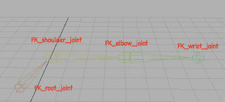
First, open up "armGeo.ma," the file I sent to you all containing a basic arm geometry. Next, build yourself a Joint chain for the FK arm: change your menu set to Animation using the pull-down option menu in the upper left hand corner of the Maya interface and from the new menus which appear select the Skeleton menu --> Joint tool and click 4 times with Grid Snapping turned on to create 4 joints at the locations you saw in class. Name them like this:

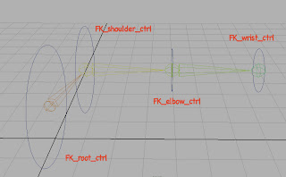
Next, build yourself a controller using the Create --> NURBS Primitives menu --> Circle tool. Make sure that Interactive Creation is turned off under the Create --> NURBS Primitives menu before you do this. You should have a brand spanking new NURBS circle in your scene now; delete its history (from the Edit --> Delete by Type menu). With the circle selected use the Edit menu --> Group command to create a buffer on the control. Name the NURBS cirlce "FK_root_ctrl" and the buffer "FK_root_ctrl_buffer," then, Duplicate (Edit menu) the new buffer three times to make 4 pairs of controls and buffers. Position them (by translating the BUFFERS, not the controllers!) at the root, shoulder, elbow, and wrist joints and name them (and their buffers) accordingly:

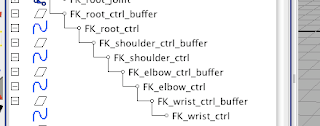
Open your Outliner by going to Window --> Saved Layouts --> Persp/Outliner (alternatively it's the third view preset button on the left hand side of the screen) and expand your view of the various controllers/buffers you've made so far. Using the Middle Mouse Button to drag a child onto a parent or by selecting first the child then the parent and pressing P, parent your FK_wrist_ctrl_buffer under your FK_elbow_ctrl, and your FK_elbow_ctrl_buffer under your FK_shoulder_ctrl, and your FK_shoulder_ctrl_buffer under your FK_root_ctrl. The finished result should look exactly like this:

Now we've got joints and controllers done. Let's make them talk to one another. Select your FK_wrist_ctrl, then select your FK_wrist_joint, and use the Constrain menu --> Orient Constraint (Options) to open up the Orient Constraint dialog box. Make sure Maintain Offset is checked, as well as All axes and press Add. Repeat this process for the elbow and shoulder. Remember to select the controller first, then the joint -- the relationship between them is "driver" and "driven," in that order. The action of the driver determines the results for the driven, so when creating constraints always select the "driver" first, then the "driven."

For the root we want to make a Parent Constraint, so this time select first the FK_root_ctrl then the FK_root_joint and select Constrain menu --> Parent Constraint (Options) to open the dialog box. Again check that Maintain Offset is active and that you are constraining to all axes and press Add. Your controllers should now be able to change the position of your joints! Try rotating and translating them to your heart's content.

Notice that translating the elbow and wrist controllers is not useful -- so let's go ahead and disable that ability. In your Channel Box, select the 3 translate channels (their names, not the numbers next to them) of your wrist controller and right click on them. In the ensuing pop-up menu, choose Lock Selected.

Your channels will now be grayed out and you won't be able to translate this controller anymore. Do the same to the scale channels, then repeat this process on the elbow control. On the root control, lock only the scale channels -- we want to be able to translate it at will.

So, now you're basically done with your rig. Clean things up a little bit by grouping your joints and controls and renaming the new parent node FK_rig.

As one final step, let's skin your arm geometry to your joints. First Delete History (Edit --> Delete by Type menu) on the arm geometry, just to get us working with a clean slate. Select the arm mesh, then select your shoulder joint and use the Skin --> Bind Skin --> Smooth Bind command to connect the skin to the bones. Enjoy!

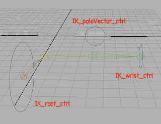
When you're finished playing with your FK arm, hide it by selecting the FK_rig group (which should contain all the nodes pertinent to your FK rig) and enter a value of 0 in the Visibility channel. Now, for the IK arm rig, we're going to repeat a lot of steps. So go ahead and create 4 new joints in the same place and with the same names as last time (exchanging the "FK" prefix for "IK"). Create three controllers the same way you did for the FK arm (again, using "IK" as your prefix) and position the wrist and shoulder controls in the same way as with the FK rig.

Your elbow control & buffer, however, should be renamed to IK_poleVector_ctrl & IK_poleVector_ctrl_buffer, respectively. Position them like so by translating and rotating the BUFFER, not the controller:

The next thing you'll need to do is tell Maya which direction you want the elbow joint to bend when you create an IK solver chain across it. This is pretty counter intuitive, so just trust me on it for now. Select your elbow joint and rotate it so that the bend in the elbow points toward the poleVector controller. It doesn't matter how far you rotate it. Next, use the Set Preferred Angle command from the Skeleton menu. Now, manually reset the elbow joint's rotation by entering a value of 0 in which ever channel you rotated it.

We can finally create our IK chain now by selecting the Skeleton --> IK Handle Tool (Options). In the tool options palette that appears, set your Current solver to ikRPsolver. Now, click on your shoulder joint, then click on your wrist joint. Ta-da! A new IK chain is created. You should see a new node in your outliner called ikHandle1. Parent it under your IK_wrist_ctrl and rename it IK_wrist_handle. Next, select your IK_poleVector_ctrl as the driver and IK_wrist_handle as the driven objects, then create a Pole Vector constraint from the Constrain menu.

You're almost finished with the basics of your IK rig. To complete it we need to make the wrist control do something to affect the rotation of the hand -- at the moment it just follows rigidly along the axis determined by the rotation of the elbow. To fix this deficiency select your IK_wrist_ctrl, then your IK_wrist_joint, and create an Orient Constraint from the Constrain menu. Remember to check that Maintain Offset is turned on under the constraint options. We should also tell the root controller how to affect the root and shoulder joints. Select the IK_root_ctrl, then the IK_root_joint, and create a Parent Constraint (Constrain menu) with Maintain Offset checked in the options dialog.

Finally, let's clean things up a little. Select the IK_poleVector_ctrl_buffer, IK_wrist_ctrl_buffer, IK_root_ctrl_buffer, and IK_root_joint and group them (from the Edit menu). Rename the resulting parent as IK_rig. Go ahead and lock off some channels you wont need on various ctrls: scale on the wrist and root controllers, and scale+rotate on the poleVector controller. If you haven't done so, skin a duplicate of your old FK armGeo to your joints in the same manner you did with the FK rig (remember that if you are duplicating after skinning you will need to unlock channels on the arm geometry and unparent it from the FK_rig group!).

Done. Play with your rig and find out if it all works. Try painting weights from the Skin --> Edit Smooth Skin --> Paint Skin Weights (Options) to adjust the way deformations propagate across joints. Try to break the rigs. When you're satisfied, turn in a single Maya scene file with the name yourName_HW06.ma before the next class for full credit.

See you on Monday!
Friday, October 16, 2009

Assignment 5: UV Texturing

Ah, UV layout. The drywall sanding of computer animation: not hard, just a pain in the ass.

With your models finalized (and hopefully with their history deleted), it's time to begin setting yourselves up to paint a texture. To do this we're going to want to adjust the model's UV Layout. By default Maya will have aligned your UVs in... a terrible fashion. So let's get on fixing that.

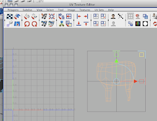
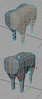
Using faces mode, select portions of your model which are relatively flat or simple when viewed from one angle (such as the entire front half of a character's body, the side of a vehicle, or the wall of a building). From the Create UVs menu choose Planar Mapping. Maya will pop up a new manipulator type with a large rectangular shape and controls at each corner. Use this manipulator to size & place your new projection, the position / angle from which Maya will attempt to apply texture data to this portion of your model. Note the lower image of this pair in which you can see the manipulator, as well as a distinct orange line which demarcates the UV Texture Border which was once the boundary around your selection. This is the line at which Maya split two adjoining sections of UVs.


In the UV Texture Editor (found under the Windows menu) you will see a 2D representation of your formerly selected components. Using the standard Translate tool, move your new grouping of UV points off the center area of your grid for safe keeping (a 2D version of the typical translate manipulator should appear in the UV Texture Editor window if you have the tool active). If you can't select the UVs to move them, right click in the UV Texture Editor and choose "UV" as the selection method and then click-drag a selection box around the UV components you are moving.

If any part of this process fails on you, I highly recommend you simply undo your way back to the starting selection (previous to executing the Planar Mapping command) and try again. Also, if you find yourself unsatisfied with the results of your projection, you can simply perform the same steps again -- creating new UV maps is non-destructive, meaning that if you get it wrong once, doing it 5 more times even without undoing won't harm your model.

Repeat this procedure with the remaining parts of your model, creating additional planar projections for other flat or semi-flat areas and Cylindrical Mappings for tube-shaped components, such as legs or the neck of an instrument. I recommend that you do not use any mapping types other than Planar and Cylindrical, especially not Automatic. Feel free to experiment, but they likely won't be of as much use in practice.

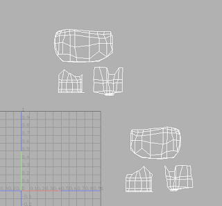
Once you have made a selection of and projected a new UV map onto every part of your model, you should have a UV Texture Editor window which looks something like this (well, if you were starting with a half-built cow model...), with parts of your model strewn about:

Translate/Scale them all down into the positive (0,0) to (1,1) area of the grid (upper right quadrant) and arrange them as you see fit. If portions of your layout are overlapping still, you may wish to go in and manually move some UVs to prevent overlapping. This is tricky to explain, but try to imagine a skinned animal being "pelted" and turned into a throw rug. All the outer facing surfaces of the animal's skin would be flattened out against a floor and none of them would overlap. This is the effect you want to go for with your UV layout.

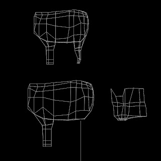
When you are satisfied with your layout, use the UV Snapshot... tool from the Polygons menu in the UV Texture Editor window to export an image of your polygon layout (Above is my UV Snapshot from in class on Wednesday which I then painted over in Photoshop to create my "What up?" cow texture). Remember the image format -- you can use anything other than "Maya IFF," but I personally recommend PNG, JPEG, TIFF, or Targa formats. Open up your UV snapshot image in Photoshop, create a new layer, and paint away. Put down whatever you like at this stage, just so long as we'll be able to see it in Maya to check your UVs when the texture is applied.

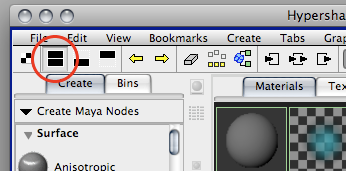
Speaking of application, go ahead and save that new painted texture of yours as a JPEG, TIFF, PNG, or Targa and open Maya up again. In the Windows menu, select Rendering Editors --> Hypershade. Create a new Lambert material from the Create bin to the left of the window. "Lambert2" or some such should appear in the topmost pane of your Hypershade window. If you can't see that pane try clicking on this button:


That will bring up both the upper and lower work panes on the right side of the window. Select your new Lambert material and in the Attribute Editor click on the little black and white checkerboard icon to the right of the Color slider. The Create Render Node window should appear. Click on the File texture icon near the top right of the list. In the Attribute Editor (third button from the top right of the main Maya window if it isn't open already), click on the folder icon next to the Image Name field in your File texture node and navigate with the file browser to your image texture file recently made in Photoshop.

Now, to finish the application, either click and drag (with the middle mouse button!) your Lambert material from the Hypershade window onto your model or select your model then right click on your Lambert material and choose Apply to Selection from the right click menu. If nothing seems to have happened, keep in mind that you might be in the wrong display mode. From the Shading menu of your Maya view panel select Hardwre Texturing from near the bottom of the list. You should now see your applied texture on your model. Ta-da!

Remember that this week is really just week 1 of texturing, so don't sweat it if not everything went smoothly. Just try all these steps and identify what doesn't make sense to you. Most important this week is for you to work on finishing your models and making sure that they are exceptionally clean without any unmerged vertexes or extra faces hiding inside them. You should email me your model file before class on Monday saved as the same thing you named it last week. Technically this is still a continuation of Assignment 4 from last week, so that name will likely be "firstName_HW04.ma". There will be another post with your Assignment 5 homework notes and more details on the UV layout process next week.

Thursday, October 15, 2009

Temporary UV Layout Guide!

Hey all, many apologies but I haven't had time yet to write up the full guide for creating your UV layouts. To tide you over until I can get it posted tomorrow afternoon, here is that image from class on Wednesday outlining the basics of the process:


Again, very sorry for this delay! Also, remember that Maya has a very robust help system / documentation included with the software. Just press F1 to activate it and search for any terms you think you remember! There are even tutorials for most of the tools you need.

Thursday, October 8, 2009

Assignment 4: Additive Modeling

So, a new week, a new model. This week's assignment will focus mostly on additive modeling, which is to say modeling by the process of combining shapes instead of extruding them. To that end you'll rough out a model with primitive shapes and then attach them with the Combine and Merge commands. A few reminders and tool shortcuts:

1.) Work Slowly and Deliberately
Remember that it's important to go back and double check your work once in a while to make sure you're not getting double extrusions, unmerged vertexes, or any number of other bizarre happenings which can occur while you are modeling. The easiest way to check your own work is to go to Component Mode, change to Vertex selection with the right-click menu, and then select some single vertexes to pull around in space. If they seem properly attached to their respective edges and faces, then all is good. It's easier to fix mistakes as they happen than to wait until a model is complete and clean the whole thing up.

2.) Try to Make 4-Sided Polygons
While Maya will compute a polygon of any number of sides, 4-sided layouts are best (and as a corollary, 4-edge intersections at each vertex are preferable as well). You will certainly run into situations where this is impossible though, such as when transitioning from a level of high polygon detail to one of low detail. In these cases, some 3 and possibly 5 sided polygons will become necessary, but use them sparingly.

3.) Attaching Shapes
When attaching shapes, you will almost always run into the above mentioned polygon layout issues. Try to plan ahead for these connections as much as possible by creating primitive shapes with matching numbers of sides (ex: an 8-sided cylinder and a 16-sided sphere are well matched). To change the numbers of sides on your primitives, go to the Create --> Polygon Primitives --> (shape name) Options Box. There you will find sliders and numerical inputs to alter the detail level of your primitives.

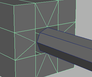
Once you have created shapes, you should begin adding detail to them with the Cut Faces and Split Polygon tools, both in the Edit Mesh menu. In this case I am attaching an 8-sided cylinder to a divided cube, so I must use the Split Polygon tool to double the number of attachment points at their intersection. Click and drag with the Split Polygon tool to position a point on an edge, release to save that position. Remember to slide points all the way to the end of an edge to lock them onto an existing vertex. You will find yourself making two triangles facing away from the high detail area of every intersection and one triangle facing toward it. You could do this with fewer triangles, but because it is a symmetrical intersection the extra triangles are preferable:

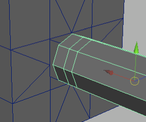
Once you have added sufficient detail to the lower detail area of your mesh, add some extra rows of edges to the other side of the connection to contain the area of transition between detail levels like so:
Now activate Point Snapping and move the vertexes of one object to match those of the other at the point of connection. Point snapping can be activated with this button (and don't forget to turn it off when you're done!):
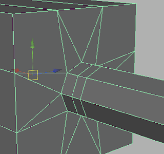
Finally, with the Mesh --> Combine function, join these two objects. You will then be able to Merge the connecting vertexes (from the Edit Mesh menu) and make a complete, continuous mesh. If the Merge function is not making successful merges, check its Threshold value and try adjusting it upwards (or downwards, if it is merging too many points). Your finished connection should look something like this:
As a last step, go to Edit --> Delete by Type --> History. This will erase the process of creation from your new object's history, which can help prevent errors from cropping up in the future. I encourage you to do this regularly.

4.) Normals
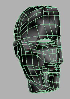
If you notice your model is developing some... blotchiness, it is likely due to a conflict in the alignment of face normals. Normals determine the direction Maya believes a polygon to be facing, so if they disagree from face to face, the rendering engine will quickly become confused and draw something like this:
Credit goes to Yueh for this fascinating piece of layout mishap -- it's an impressive bit of modeling for a first assignment, too! To "fix" this problem, simply go to the Normals --> Conform command. Of course, it won't have really fixed the problem, because the true problem is caused by having multiple faces overlapping in the same area (lamina faces), and the only solution we've seen in class so far is to go in by hand and delete one of every face. But at least it'll look nicer for now!

5.) Plan Ahead
Don't forget to do some planning. Get out a sheet of paper and either draw or write down how many "parts" your model really has. Then make each part separately, either by extruding it from a central cube or by making them from separate primitives then combining them. Planning here is everything here, and the more of it you do the fewer your headaches will be.


Other than those tips, all I can say is good luck! When you're finished, email me the Maya scene file (remember, ".ma" format) before Tuesday (no class on Monday!) with the naming format "firstName_HW03.ma."

Thursday, October 1, 2009

Assignment 3: Extrusion Modeling

So, it's time to do some modeling! We're going to be starting with the Cube as our basic unit in this lesson, slicing it in half, mirroring it, and then using the Extrude and Cut Faces tools to expand it into a model. A few reminders:

1.) Mirroring a model.

To mirror a model, you'll want to first create a cube, then switch to your Front view panel, using the space bar to go in and out of the 1-up and 4-up view modes. In the front view, with your cube selected, bring up the Edit Mesh --> Cut Faces tool and click-drag to make a cut. Try to line your cut up with the vertical center line of the screen, thus cutting the cube in half cleanly. Hold sown the Shift key to force the Cut Faces tool to lock at 45 degree angles, which will make the creation of a perfectly vertical cut easier.

Once your cube is cut, switch to Component Mode (hotkey: F8), then right click on the object and use the ensuing menu to activate Faces selection. With the Selection tool active, select all the faces on the left side of your newly cut cube and delete them. With the F8 key, go back to Object Mode. Now, from the Edit --> Duplicate Special (Options) menu, create a mirrored copy of the half-cube. Set the Geometry Type to Instance. If you cut it vertically in the front view you'll want to set the Scale to -1 in the X axis. Remember the axis color code if you're not sure (Red = X, Green = Y, Blue = Z)!

2.) Extruding

To extrude a face from your object, switch to Component Mode (F8), activate Faces selection (right click menu), select one or a group of faces, and go to the Edit Mesh --> Extrude command. Your manipulator will immediately change to a new type, and you should switch back to the regular translate tool. Now just pull your new extruded faces in whatever direction you desire! Don't forget that even if you forget to pull the new extruded faces out from their starting location they have still been extruded. If you forget about them you'll soon discover some very funky stuff happening to your model (many of you have already experienced this).

If you run into the problem of extruded faces splitting apart after extrusion, go to the Edit Mesh menu and check that Keep Faces Together is checked.

3.) Planning

Don't forget to plan! Look at some reference and get a basic idea of the layout of your object before you begin attacking it. If you're creating a dog you'll know that it needs at least four protrusions from the bottom from which to sculpt legs, so cut your base cube up to accommodate for them. It is much easier to make the majority of your cuts / extrusions before you begin pushing and pulling vertexes to shape your model.

4.) Don't be Afraid to Start Over

Really, don't. It will go so much faster to make the same model the second time, you won't even believe it. So if things get really messed up and you can't figure out why your polygons are exploding everywhere, just start over! It won't take you nearly as long as you think.


When you're finished, email me your Maya scene file with the name firstname_HW03.ma by Sunday at midnight for full credit. And be creative!